How To Conact Resistor In A Circuit Board Diagram All Types
Resistor wiring pngwing w7 End of line resistor height Circuit note: how to read a resistor resistors are one of the main
Circuit Note: How to Read a Resistor Resistors are one of the main
Load resistor 12 volt. twin pack br122 Circuit diagram series and parallel Wiring diagram for motorcycle led indicators
Resistor resistors resistance multimeter calculation
Resistor schematic symbolWiring resistors diagrams Resistor diagramsWhat is a resistor? construction, circuit diagram and applications.
Resistor circuit diagrams: understanding connections and functionsCircuit design Circuits diagram resistorResistor circuits resistors electrical wattage schematics resistores identifying resitor wiring jameco chemical note low decode teknik elektro afkomstig smd blocks.

[diagram] 1969 ford resistor wire diagram
V rheostat wiring diagramResistor : construction, circuit, working, properties & its applications Solved 1.) you have one resistor. to build a simple circuitElectronic basics.
Series circuit diagram with resistorResistor symbols 94 pdf resistor color chart 3 band printable hd docx download pdfResistor wiring diagram / radiator fan resistor wiring scheme please.

Resistor circuits wiring parallel resitor wires components
Potentiometer schematicResistor electronic electronics tabel kode Electric circuit resistors in parallel definition and diagram imagesResistor circuit diagrams: understanding connections and functions.
Circuit parallel resistors circuits schematics current basicAll types of resistor symbols and diagrams Resistor wiring diagram / ford ballast resistor wiring diagramEnd of line resistor wiring diagram.

Resistors & wiring diagrams
Diy led turn signalsWiring diagram for resistors to correct the flash rate. .
.


Resistor Symbols
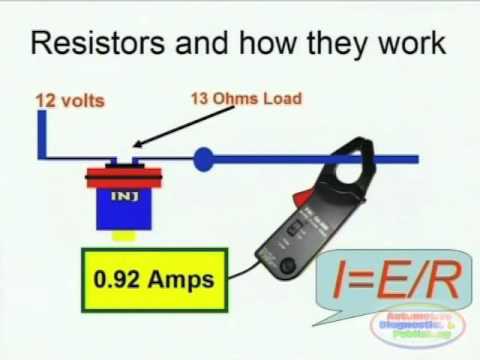
Resistors & Wiring Diagrams - YouTube
![[DIAGRAM] 1969 Ford Resistor Wire Diagram - MYDIAGRAM.ONLINE](https://i2.wp.com/cimg4.ibsrv.net/gimg/www.f150forum.com-vbulletin/713x433/80-load_resistor_wiring_diagram_f2cdac1dd6aa6a8db0b09e01aa38194d195ef088.png)
[DIAGRAM] 1969 Ford Resistor Wire Diagram - MYDIAGRAM.ONLINE

Circuit Diagram Series And Parallel

Electronic Basics

Wiring diagram for resistors to correct the flash rate. | Honda CB1000R

Electric Circuit Resistors In Parallel Definition And Diagram Images

Circuits Diagram Resistor